Initial situation: Two LANCOM routers are connected via a WAN link. The requirement is to establish a secure VPN connection between them by means of IKEv2/IPSec VPN. The routers are a LANCOM 1800VAW at the main office and a LANCOM 1800VA-4G at the branch office.
Note: We assume that a WAN connection exists between the two devices.
-
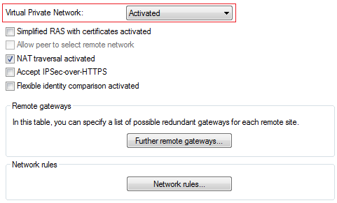
Enabling VPN: For both of the routers, open the menu item and, under Virtual Private Network, select the option Activated. This enables VPN on that specific device.
-
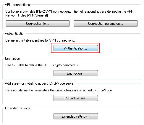
Configuring the authentication: Specify the type of authentication for the VPN connection. To do this, open the menu item and click the button Authentication.
-
Click on the Add button to configure a new authentication type. Enter the information for the authentication of the VPN connection into the configuration window.
Note: The screenshots below show the configurations for both devices for direct comparison side by side. Here we only describe the configuration parameters that differ from the default values.
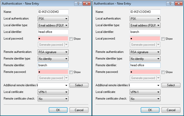 Note: The left half of the images shows the LANCOM 1800VAW, and the right half shows the parameters of the LANCOM 1800VA-4G.
Parameter Description Name Enter the name for the authentication here. In this example, ID-IKEV2-DEMO was entered on both devices. This entry is used later in the VPN connection list. Local authentication Select the authentication type used on this router. This example uses authentication by pre-shared key (PSK). Local identifier type Select the identifier type used on this router. In this example, the identity type was set to E-mail address (FQUN). Local identifier Set the local identifier. In this example, the local identifier was set to Main on the 1800VAW and Branch on the 1800VA-4G. Local password The pre-shared key required to successfully authenticate at this router. Remote authentication Select the authentication type used by the remote router. On the 1800VAW, this entry corresponds to the entry for "Local authentication" on the 1800VA-4G. Remote identifier type Select the type of the remote identifier (used by the remote router). On the 1781AW, this entry corresponds to the entry for Local identifier on the 1800VA-4G. Remote identifier Enter the identifier of the remote station. On the 1781AW, this entry corresponds to the entry for "Local identifier" on the 1800VA-4G. Remote password The pre-shared key required to successfully authenticate at the remote station. On the 1781AW, this entry corresponds to the entry for Local password on the 1800VA-4G. -
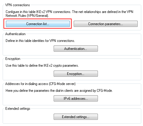
Configuring the Connection list: Configure the connection lists on each individual router. To carry out the configuration, open the menu item and click the button Connection list.
-
Create a new VPN connection by clicking the button Add.
Note: The screenshots below show the configurations for both devices for direct comparison side by side. Here we only describe the configuration parameters that differ from the default values.
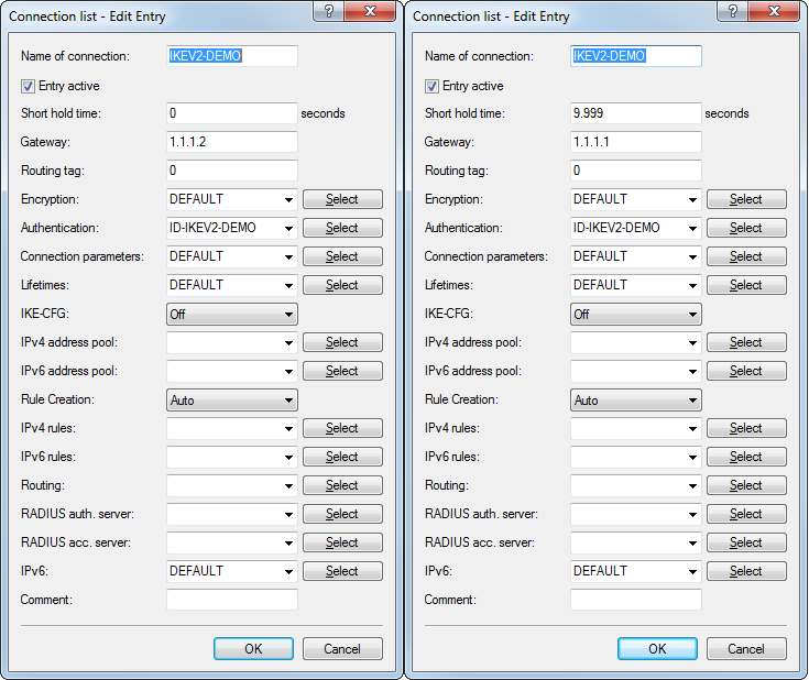 Note: The left half of the images shows the LANCOM 1781AW, and the right half shows the parameters of the LANCOM 1800VA-4G.
Parameter Description Entry active Set a check mark in the check box to activate the connection. Name of connection Enter a name for the VPN connection. This name is used later in the routing table. Short hold time Specify the short-hold time in seconds for the VPN connection. In this example, the value for the 1781AW is set to 0. This means that this router will not actively establish the VPN connection. The value for the 1800VA-4G is set to 9999. This value means that the router will not actively disconnect and, in case the connection is lost, it reconnects immediately. Gateway Specify the IP address of the remote station. In this example, the IP address of the WAN interface of the 1781AW is 1.1.1.1 and that of the 1800VA-4G is 1.1.1.2. Important: If the 1800VA-4G has a dynamic IP address, then the value for the remote gateway on the 1781AW needs to be set to 0.0.0.0 instead of 1.1.1.2.Authentication Select the authentication. The entry here corresponds to the name of the authentication that you set in step 3. -
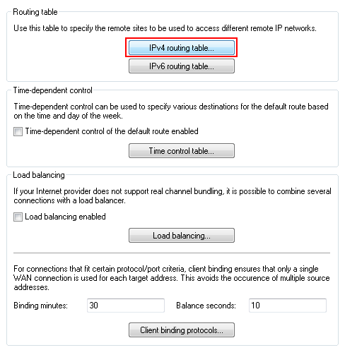
Configuring the Routing table: Configuring the routes here ensures that packets can be sent from the router through the VPN tunnel to the VPN remote station. To do this, open the menu item and click the button IPv4 routing table.
-
Create an additional route by clicking the button Add. Information about the route is entered into the configuration window for each router.
Note: The screenshots below show the configurations for both devices for direct comparison side by side. Here we only describe the configuration parameters that differ from the default values.
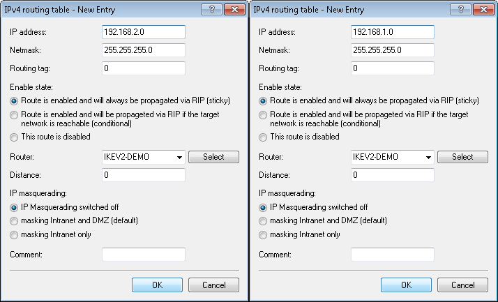 Note: The left half of the images shows the LANCOM 1781AW, and the right half shows the parameters of the LANCOM 1800VA-4G.
Parameter Description IP address Enter the IP network to be accessed via the VPN tunnel. In this example, the IP network 192.168.2.0 should be accessed from the 1781AW and the IP network 192.168.1.0 should be accessed from the 1800VA-4G. Netmask Specify the netmask of the IP network named above. Enable state Select the option Route is enabled and will always be propagated by RIP. This activates the entry and makes it available for use. Router For the router, enter the name of the VPN connection that you entered in step 4. IP masquerading Select IP masquerading switched off so that the router does not conceal the other network behind its own IP address.